A multimeter is a device that helps you measure voltage, current resistance, or temperature (in some models). You can use them on an automotive or your HVAC system at home or in the office. Multimeters are either analog or digital, and both can test for amps, ohms, voltage, and resistance.
A multimeter is the ideal go-to tool for electricians whenever they face bad wirings, grounding issues, or common malfunctions in devices. It pinpoints the exact nature of the problem along with the location of the problem.
Table of Contents
What Do the Symbols on a Multimeter Mean?
If you look at your multimeter, which helps measure voltage, current, or resistance, you’ll not see these words written on the device. But this shouldn’t scare you as there is a better way these are indicated on the meter.
The three electricity elements have an abbreviation that represents their measurement units. These are the symbols on a multimeter. For example, voltage is presented by ‘V,’ which shortens the long word. However, the three main symbols are not the only ones in a multimeter, as there are several others that we’ll look at too.
Symbols have been used to represent objects, parameters, words, etc., through the dawn of time. For example, in the electrical language, each parameter is associated with a unit of measurement. The most commonly known system of measurement is System International (SI)
The SI system uses different symbols to represent the unit of measurement. For example, symbols on a multimeter represent the SI unit of the parameter (e.g. current, voltage, etc.) that you want to measure.
A good understanding of these symbols will prevent you from wrong interpretations while reading the multimeter. In addition, it will help you from having the wrong setting while doing a certain test which can be dangerous. So read up to the end and learn more about multimeters symbols.
Digital Multimeter Symbols and Meanings
Do you find it hard to understand the symbols on a multimeter? This is normal, especially if it’s your first time using a multimeter. However, multimeters contain several symbols, switches, and buttons, giving you a hard time interpreting them.
This article will help you understand these symbols. It will also help those who have been having their multimeter for a while but are unsure of some symbols.
To shed some more light on the topic, we have explained the different symbols that exist on a digital multimeter. But don’t worry, almost all the multimeters have similar symbols and functions as well.
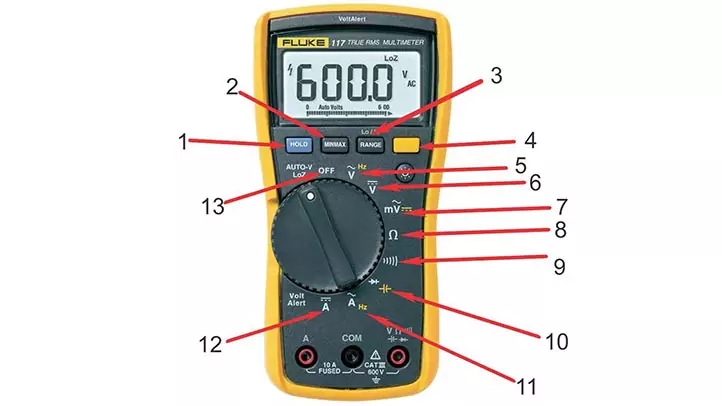
1. Hold Button
This button enables you to ‘hold’ the readings on the multimeter after doing a test. It helps you refer to the reading later after working in a poorly lit area that couldn’t enable you to see the screen.
It’s found on the top-left corner of your multimeter. The top notch multimeters have this button to enable the users to freeze their reading on the multimeter screen.
2. Min/Max Button
This button has input values, and it beeps when there’s a wrong connection. It also helps you capture the highest values of signal errors in microseconds. When you turn on this setting, it will record and hold the highest and lowest signal level readings.
The first Press on this button makes the multimeter show the max value. The second Press is for the min value. This button is also used to save the minimum and maximum values. A beep is audible when the previous minimum/maximum value is breached.
3. Range Button
It is the button at the top of your multimeter containing the ‘Lo/Hi’ symbol. It helps you select different ranges on the multimeter.
Most digital multimeters have both manual-range and auto-ranging. But others require you to select the range for specific tests manually. To turn to auto-ranging mode, press the hold and range buttons. This button allows the users to select a particular range.
4. Function Button
This is the yellow button that activates secondary functions like capacitance and temperature around the dial. It also helps you switch off and, on your multimeter, when not in use.
You can also use this button to hold data or select diode-test. The secondary function of a digital multimeter is enabled using this button. These secondary functions often appear as yellow text or symbols.
5. AC Voltage
The AC voltage enables you to test for voltages in an electrical component. It is signified by the symbol ‘V‘ and a wavy line on top of it. It shows readings between 100-240 volts. This setting enables you to check for alternating currents on devices like TVs, fans, or kettles. In addition, it shows the voltage of your electronic component.
The multimeter represents the direct current voltage with the symbol V~. On some multimeters, you would find the letters “ACV” written instead of the symbol.
6. DC Voltage
DC voltage is symbolized by the letter ‘V–‘ with three hyphens above it and a straight line on top of the hyphens. It’s for use in small electronic circuits, batteries, or indicator lights. If the current in the device you’re checking is very high, the multimeter will read ‘OL.’
The multimeter represents the direct current voltage (DCV) with the symbol V–. On some multimeters, you would find the letters “DCV” written instead of the symbol.
7. AC Millivolts (mV)
The symbol for this setting is ‘mV’ and a squiggly line above the ‘V’. It enables you to test for smaller circuits to get accurate and fast readings. It’s better than using the AC voltage setting, which gives a low reading.
This button is used to measure the AC voltage of smaller circuits. The same button can measure the DC voltage of small circuits by pressing the function button.
SHIFT: DC Millivolts: You can measure DC millivolts Once you insert the dial point on AC millivolts symbols and press the function button. You can use this button for the smaller circuit.
This symbol also resembles the road symbol, but it contains three hyphens and a straight line on top of mV. Thus, it gives accurate measurements in circuits with low voltage. But it should be used on devices that have direct currents, like batteries.
8. Resistance Button
The SI unit of resistance is known as the “ohm”. The symbol for resistance is Ω. A high resistance reading on your multimeter shows the electric current is finding challenges to flow. It’s measured in ohms, and a higher resistance reading indicates low current flow in a device. The resistance button enables you to test the effectiveness of switches or relay contacts.
This (Ω) symbol enables you to get accurate resistance reading. It also lets you identify if your fuse has blown. The ‘OL’ symbol on your multimeter is an indication the fuse needs to be replaced. When using this setting, ensure the fuse is out of the circuit.
9. Continuity Button
This button has symbols that are similar to those on PCs which represent sound. When your multimeter detects continuity between two circuits, it will produce audible sounds. It enables you to find open or short circuits. The button helps you check for connection problems in electrical components.
To check if a circuit is complete with a multimeter, continuity is used. The continuity button works by sending a small amount of current into the circuit and checking if it reaches the other end. A wave or a diode represents the continuity symbol on a multimeter.
10. Diode Test Button
This symbol is used to check whether you have a good or a bad diode. The symbol looks something like an arrow and a positive sign coupled together “→+”. It’s the most reliable way, unlike when you use Ohm settings.
11. Alternating Current
The symbol for alternating current is ‘A ~‘ with a squiggly line on top. This symbol represents the measurement of the alternating current of a device. It checks for current loads in a circuit, but you need a clamp attachment to perform this function. Also, when conducting this test, you need to be careful as AC is dangerous.
12. Direct Current
This feature enables you to check for current in amps in a direct current. You can use it on laptops or automotive. It is represented by ‘A⎓‘ three hyphens above it and another straight line. Direct current is present in almost all portable electronic devices.
13. On/Off Button
This button acts as a switch to turn On and Off the multimeter.
14. Auto-V/LoZ Button
Some of the latest models of multimeters have this button. It prevents the wrong measurements due to ghost voltage.
Table could not be displayed.Fluke Vs Klein Multimeter Symbols

There’s no major difference between the symbols in Klein and fluke multimeters. However, the shows a scale of ranges for every symbol in a central place around the function selector switch. Klein multimeters also have fewer buttons, unlike the fluke meters.
But the symbols on a fluke multimeter are found in most multimeters, making it the best to use for illustrations.
Multimeter Symbols pdf
If you are interested to learn in detail about digital multimeter symbols and their functions, click here for the multimeter pdf
How to Read Symbols on Analog Multimeter?

The reading on an analog meter is not too difficult to understand the thing to remember is the range the multimeter is set to.
The range has to be multiplied by the set range to get the correct reading.
For example, if the resistance range is set to 50 and the multimeter needle points to 25ohms, you’ll need to take a product of 25 and 50 hence giving the actual resistance of 1250ohms.
How to Read Symbols on a Digital Multimeter?
Reading a digital multimeter is a lot simpler as compared to the Analog version. Connect the red probe to the socket labeled with a “V”, and the black probe should be plugged into the socket labeled “COM” set the knob towards the parameter you want to measure. The digital multimeter comes with a built-in screen display.
All you need to do is to look at the display screen and note down the required reading. Sometimes, a multimeter not showing a reading could mean that you have not pointed the knob toward the correct parameter.
Different Parts and Functions of a Multimeter
A multimeter has four main parts, which makes it perform better. They include;
Display
 The multimeter’s display lets you see the reading from the different tests you’ll conduct. In simple terms, it’s the screen. The display has four digits and can show a negative sign.
Some multimeters have illuminated displays that prevent you from straining your eyes while working in dark areas.
If you have an analog multimeter, the display will have a needle pointer that shows the value you’re testing for on a multimeter.
Buttons and sockets
these features vary from every multimeter as some have more buttons and sockets than others. The buttons help you adjust and control the multimeter. They include the voltage button, resistance button, function button, and many others. Related: Best multimeters 2023
Dial/rotary switch
This part is used to select the unit of measurement. It allows you to change what you’d wish the multimeter to test, like current, voltage, or resistance. Some multimeters have manual ranging while others are auto-range multimeters.
The auto-ranging multimeters are easy to use, unlike the manual ones, which require manual range selection. The auto-ranging meters only require adjusting the dial to your preferred setting, connecting the test probes, and automatically getting the readings.
Input ports/ jacks
These are holes where you get to insert the test leads. The test leads are wires that connect your multimeter to the equipment you want to do the tests on. The wires need to be insulated, and each has got its color.
For example, the red test probe is for the positive terminal, while the black one is for the negative terminal.
Table could not be displayed.FAQs: 5 Questions & Answers (Multimeter Symbols)
What does DCV stand for on a multimeter?
This means Direct Current Voltage. It’s a setting used to check for direct current voltage in batteries.
What are the basic electrical symbols?
The basic electrical symbols are capacitator, fuse, inductor, switch, antenna, and transformer.
What does 200m mean on a multimeter?
200M means 200 milli. It is the maximum value your multimeter will show if you set the knob there.
How do you read a 12V on a multimeter?
To read 12v on a multimeter, set the multimeter in a range that can work perfectly to get the right results. For example, to read the 12V, use the 20V setting.
What do 6000 counts mean on a multimeter?
It means that the multimeter will have a maximum of 5999 on the display.
How do you read a DVC multimeter?
You need first to adjust the dial to DCV. Then put the black test probe in the COM jack. After that, insert the red probe in the voltage jack and connect both probes to the negative and positive circuit terminals. The reading will be on your meter’s display.
What does M stand for in a multimeter?
M stands for mega or million.
How do you read a 20k ohm meter?
To read this, you need to set your multimeter to the 20k ohm setting. If this ohm range setting is greater than that of your multimeter, it will show a zero.
What does HFE mean on a multimeter?
This is a measure of the direct current gain of a junction transistor. It means a mode where the multimeter can test for the HFE of a transmitter.
Final Thoughts
Understanding the multimeter symbols helps you avoid making common mistakes that can cause accidents. It also enables you to work with fewer challenges as you’re aware of what every symbol means.
Remember the voltage symbols on the multimeter and multimeter dial symbols have the same result for and .